Physics 103 - Experiment 6 - Circuit Basics
Introduction
Goals
The goal of this lab is to learn how to analyze and measure basic properties of circuits. You should have already learned about the basic elements that make up a circuits:
- Voltages
- Currents
- Resistors
Equipment check
Please make sure your station has all of the following items. If not, check again, then talk to your lab instructor.

- Circuit Experiment Board (CEB)
- Digital Multimeter (DMM)
- Two D Batteries
- Seven Resistors (varying resistances)
- Wire Leads (straight ends – 7 pieces; alligator clip ends – 5 pieces)
Warm Up Exercise
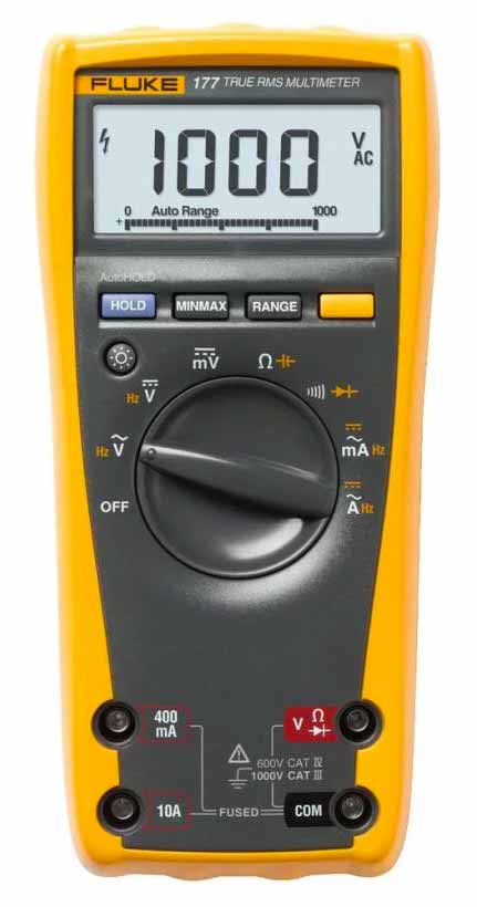
The Fluke Multimeter
On the desk is a yellow instrument called a multimeter. It's probably one of the best things ever invented. It can measure many different electrical properties quickly. We'll use it to measure Resistance, DC Current and DC Volts.
Since it is a multimeter, there are different modes of operation and you'll need to make sure it's setup to measure the specific quantity you need to measure. Get familiar with the multimeter and its rotary switch which selects the specific quantity you wish to measure
Do note the yellow printed quantities/symbols (eg Hz) which are accessed using the yellow button located to the right of the ‘Range’ button, and functions in the same way as 2ND function on your scientific calculator.
Sort and measure your resistors

Measuring the resistance of a resistor
Use your bench digital multimeter (DMM) to measure resistance of each resistor at your workstation.
- First, the rotary switch should be directed to the Ohm symbol which looks like this: Ω
- Next make sure the Black test lead is connected to the port labeled COM. This is effectively the ground or zero potential.
- Red test lead should be connected to the plug above COM labeled: V
Write down the resistances on a piece of paper, and then keep your resistors sorted on that paper.
Measure a Voltage
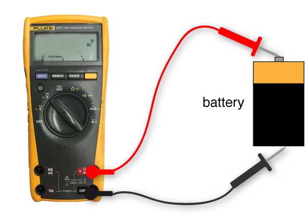
Measuring the voltage of 1 battery
Now, we'll use the DMM to measure the voltage of your batteries.
- Make sure the red lead is plugged into the V terminal, and the black lead is connected to the terminal labeled COM.
- Set the DMM to the DC Voltage measurement setting:

- Connect the red lead to the positive terminal of the battery, and the black lead to the negative.
- You should measure approximately 1.5 V for a single battery. Enter your exact value below:

Two batteries in series, and measuring the voltage.
Now, we'll combine the batteries in series so that we effectively add their two voltages together.
Put both batteries in the circuit board, and measure the voltage of both batteries. You should obtain around 3 volts for both batteries together. Enter your exact value below:
Measure a Current

A diagram of a current measurement.
Now, for our last basic measurement, we will measure the current through a simple circuit. You need to change the terminals of your probes on the multimeter, as well as the mode switch on the multimeter. Use the 100 Ω resistor and 1 battery.
Instructions:
- Make sure the red lead is plugged into the 10 A terminal, and the black lead is connected to the terminal labeled COM.
- Set the DMM to the DC Current measurement setting (labeled
A). You'll need to press the Yellow Button to change from AC to DC measurements. - Connect the red lead to one end of the resistor, the other end of the resistor to the positive side of the battery, and the black lead to the negative end of the battery
Now, repeat the measurement, but change the multimeter to measure on a milliAmp scale. You'll need to:
- Move the red cable to the mA connection,
- and adjust the selector knob to the 400 mA setting. (make sure the meter is also set to DC measurement, not AC)
- Repeat the measurement and report your value in milliAmps.
Experiment 1: Build a simple circuit
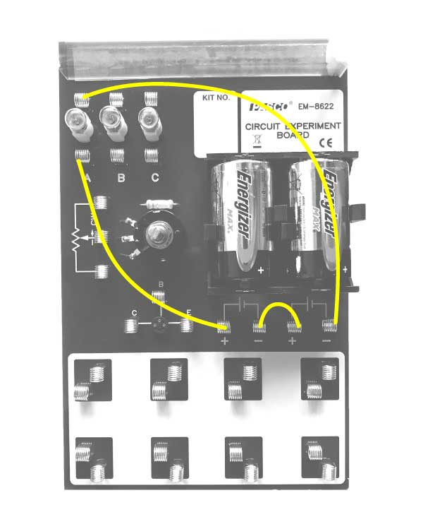
Simple Light bulb circuit: photo
Build a simple circuit to illuminate one of the bulbs on the circuit board using both batteries. Follow the image shown of the circuit. Shown are two representations of the circuit: a) a photo of the board with wires drawn on it, and b) a circuit diagram showing the components using symbols. As we move on in the lab, we'll show less pictures and more circuit diagrams, so make sure you can understand the translation between these two modes of visualization.

Simple Light bulb circuit: diagram
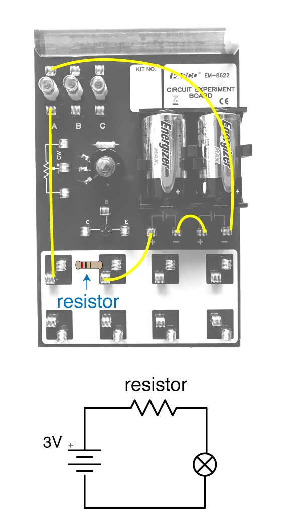
A light bulb + resistor in series.
Next, we'll want to add another component to this lightbulb circuit: a resistor.
Assemble the circuit as shown, using the resistor with the highest value from your collection (probably around 500 Ohms).
What do you observe the light bulb doing in this configuration? Also, try to come up with an explanation for your observation.
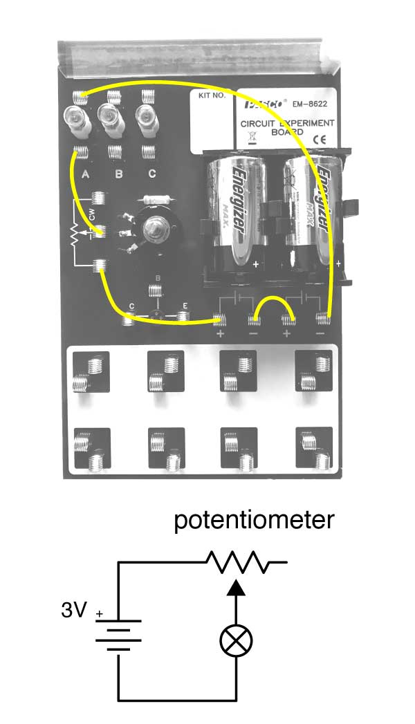
Light bulb with a potentiometer in series.
Now, we'll add a new component: the Potentiometer. It's the thing on the board that has the little knob you can turn.
Construct a circuit using the diagram shown. This circuit will connect the light bulb to the batteries, but it will add the potentiometer in series with the lightbulb. A potentiometer has a little knob the you can turn and it will change something about the circuit.
After constructing the circuit, turn the potentiometer knob and observe what happens. Write your observations and try to come up with an explanation for what is happening. Can you think of a simple experiment using the multimeter that would test your hypothesis?
Report Questions
Discuss your observations with this simple circuit and how changing the potentiometer knob affects the lightbulb. Hypothesize about what the potentiometer could be doing the circuit.
Experiment 2: Test Ohm's Law
Introduction
Ohm's law is the basic mathematical relationship between Voltage, Current, and Resistance: $$V = IR$$ The next section will work towards showing that this relationship is true (to the best of your measurement abilities!).
When trying to demonstrate a relationship like the one summarized by Ohm's Law, the best method is to create a table of data and then use that table to make some plots.
Using your new skills with circuits and the multimeter, connect a resistor in series with one battery.
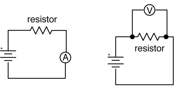
Left: Circuit for measuring current with a single resistor. Right: Circuit for measuring the voltage across a resistor.
- Make sure your multimeter is connected to the two leads using the COM and the 400 mA plugs.
- Make sure the ammeter is set to measure DC current on the mA scale.
- Measure the current passing through the circuit using a 100 Ω resistor.
- Disconnect the multimeter from the circuit, and change the settings and lead configuration to know measure the voltage across the resistor.
- Make a table of data with all your measurements like the one shown below.
- Repeat for 3 (or 4) resistors
| Voltage (V) | Current (A) | Resistance (Ω) |
|---|---|---|
Analysis
Take your table and enter the data into Excel. Then create an x-y scatter plot with the vertical axis being resistance and the horizontal axis current.

Example data set from this experiment.
This graph shows the type of graph you should expect to create when plotting your data.
The next step, which you can do now or later, will be to extract a fit from your data points. The function you are fitting is a slight re-arrangement of Ohm's Law:
$$R = V\left(\frac{1}{I}\right)$$
When you fit (using the Add Trendline option) you can choose a power law fit. A power law just means the independent variable is raised to a power (an exponent). In this case, that exponent is -1 since the equation of Ohm's law with current as the independant variable is just:
$$R = V I^{-1}$$
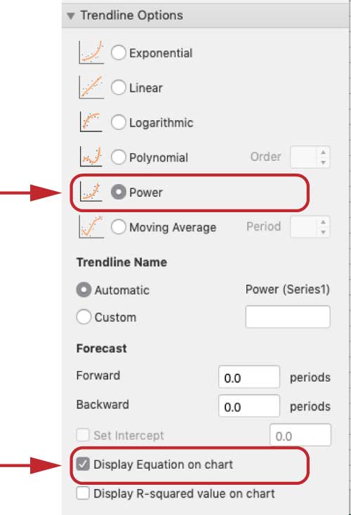
The setting for fitting your line.
The constant term in the equation that is generated by your fit should be the same as the Voltage produced by your battery.
Report Questions
Show how your data demonstrates the validity of Ohm's Law. Include your table of data plot, fits, and any mathematical derivations you find relevant.
Experiment 3: Test Ohm's Law, again
This time, you'll want to change something else in the circuit, rather than the resistance, and see how the current varies. The only other thing we change is the voltage. So, build a circuit that measures the current passing through a 100 Ω resistor. Do it for one battery, (~1.5 V) and then for two batteries (~3 V). Though you should also measure your voltage from each configuration since it might be a little different than 1.5 or 3.
| Voltage (V) | Current (A) | Resistance (Ω) |
|---|---|---|
Fill in your table of data, and use it (by fitting a linear trendline to your plot), to confirm that: $$V = RI$$ In this case, you are changing $V$ and $I$, but keeping R constant. Current $I$, is the independent variable. The value of $R$ is effectively the slope of the line on your graph.
Report Questions 2
Show how your data demonstrates the validity of Ohm's Law. Include your table of data plot, fits, and any mathematical derivations you find relevant.
Experiment 4: Resistors in Series and Parallel

Fluid flowing as an analogy for circuits.
An analogy: As water (or blood or any fluid) flows through a channel (or vein), it can encounter constrictions along the way. It can also encounter forks and splits in the channel. Depending on how these constrictions and split are arranged, the geometry can either be considered in series, or in parallel. See the diagram for examples of each case.
As you do the next section, refer back to this analogy to aid in your conceptual understanding of the various circuits.
Exp 4, part 1: Resistors in Series
Using your skill with the multimeter and circuits, build a simple circuit with 2 resistors in series.
Confirm the following:
- That the total resistance across both resistors ($R_{1+2}$) is equal to the sum of the individual resistances ($R_1$ + $R_2$)
- That the sum of the voltage drops across the individual resistors is equal to the total voltage of your battery (the voltage source).
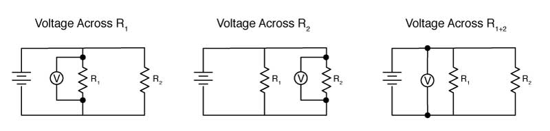
You can choose which two resistors to use. The following schematics will help you understand how to measure the Voltage across a resistor. Also, use Ohm's law to calculate the current through each element of the circuit.
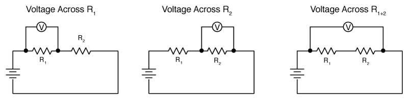
Three voltage measurements
You'll want to construct a table of table like the following:
| Resistance | Voltage Across | Current through | |
|---|---|---|---|
| $R_1$ | |||
| $R_2$ | |||
| $R_{1+2}$ |
Before going on, enter your value for the total voltage of your source, and the current this circuit will create.
Exp 4, part 2: Resistors in Parallel
Now, re-arrange your circuit to check the following statements for 2 resistors configured in parallel.
- That the resistance in this configuration follow the parallel circuit laws: $$\frac{1}{R_{1+2}} = \frac{1}{R_1}+\frac{1}{R_2}$$
- That the volatge drops across both resistors is the same and equal to the voltage drop across the battery (the source)
- That the sum of the current passing through each resistor adds up to the total current in the circuit.
Circuit diagrams for resistors in parallel.
You'll want to construct a table of table like the following:
| Resistance | Voltage Across | Current through | |
|---|---|---|---|
| $R_1$ | |||
| $R_2$ | |||
| $R_{1+2}$ |
Before going on, enter your value for the total voltage of your source, and the total current this circuit will create.
Report Questions
- Articulate the difference between resistors in parallel and in series.
- Show, based on your measurements, that the rules for resistance addition are true: $$R_{1+2} = R_1 + R_2 \;\; \textrm{in series}$$ $$\frac{1}{R_{1+2}} = \frac{1}{R_1}+\frac{1}{R_2} \;\; \textrm{in parallel}$$
- Use Ohm's Law to show that the currents passing through each resistor for the parallel circuit match or are close to your measured values.