Physics 204 - Lab 4 - Induction
Introduction
Goals
In this lab you will measure the induced currents due to a changing magnetic field.
Equipment check

Please make sure your station has all of the following items. If not, check again, then talk to your lab instructor.
- 1 Oscilloscope
- 1 Large Coil apparatus
- 1 Small solenoid (3" coil)
- 1 Galvanometer
- 1 Ammeter
- 1 Variac
- 1 Oscilloscope
Basic Concepts
Induction is summarized by the following formula:
$$\bbox[10px, border: 2px solid red]{\mathcal{E} = -\frac{\Delta\Phi_B}{\Delta t}}$$In words, it says: the magnitude of the emf $\mathcal{E}$ induced in a conducting loop is equal to the rate at which the magnetic flux $\Phi_B$ through that loop changes with time.
In your own words, what is on the left hand side? What does it mean?
In your own words, what is on the right and side? What does it mean?
Activity 1:
On the desk you'll see a small wire coil about 2-3 inches long with two connectors on it. There will also be a Galvanometer, which measures small currents. Get a coil, and connect it in series with the Galvanometer (one wire goes to the black socket labeled 0, the other goes in the red, try 500 μA). This will serve as our loop.

Now we need to change the magnetic flux through the loop. Pick up one of the bar magnets also on the bench. This is a permanent magnet which means it always has a magnetic field.
Measure an induced current:
While pressing the Push to Read button on the ammeter, insert the bar magnet into the coil which watching the needle on the galvanometer.
What is the maximum current you can generate in the coil?
What actions can you take to generate the largest deflection of the galvanometer needle?
How can you make the needle deflection smallest while still passing the bar magnet through the coil?
Why does the needle sometimes go to the positive side? And sometimes to the negative side?
Understanding Induction
Reading
Please read the following section and do the math associated with it before attempting experiment 1.
The overall structure of the first experiment below will be to pass a time varying current through the large coil apparatus and use the small search coil to measure the strength of the magnetic field it creates by measuring the induced EMF. Later, we'll change the position and orientation of the search coil to learn about the magnetic field distribution.
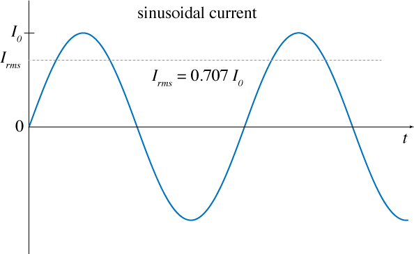
The current being applied to the large coil is an alternating current (AC), which means it follows a sinusoidal function. $$I(t) = I_0 \sin \left( 2 \pi f t \right)$$ Here, $I_0$ would be the max amplitude of the current and $f$ is the frequency of the AC. The $f$ in this case is 60 Hz. The $I_0$ is controlled by the Variac. The ammeter measures the Root Mean Square (RMS) of the oscillating current, which is related to the max current $I_0$ by: $$ I_\textrm{rms} = \frac{I_0}{\sqrt{2}} $$
Calculation Question:
If the ammeter reads 1 amp, what is the actual maximum amplitude of the signal?
Here is the apparatus. We'll need to distinguish the two coils, so lets call the small coil, Coil 1, and the large coil Coil 2 for the following math. Also, the geometry of the two coils is important. This table shows the diameter of each, and the number of turns, $N$.
| Coil 1 | Coil 2 | |
|---|---|---|
| d | 5.0 cm | 48.4 cm |
| N | 1000 | 400 |
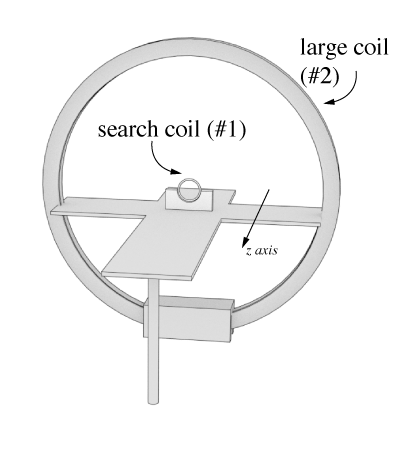
The field strength (in the z direction) exactly as the center of the large coil will be given by the following, derived from the Biot-Savart law. $$ \begin{equation} B_z = \frac{\mu_0 N_2 I}{2 R_2} \label{eq:fieldcenterloop} \end{equation} $$ where $N_2$ is the number of turns of the large coil, $I$ is the current applied, and $R_2$ is the radius. $\mu_0$ is the Magentic Permeability of free space and is equal to $4 \pi \times 10^{-7}$ N/A2. The magnetic flux through the small coil (#1) will be given by: $$ \begin{equation} \Phi_B = B A_1 \cos \theta \label{eq:fluxthroughsmallcoil} \end{equation} $$ where $B$ is the magnetic field, $A_1$ is the area of the loop ($A_1 = \pi R_1^2$), and $\theta$ the angle between the direction of the field and the normal to the loop area. We can make the assumption that the field is uniform over the size of $A$ and is parallel to the surface normal.
Calculation Question:
What should the magnetic flux through the small coil be when the current through the large coil is 1 amp?
The next thing we need to do is evaluate the time derivative of the current since that will be the only factor in the flux equation that changes as a function of time (since $B$ depends on $I$ and $I$ is changing). $$ \begin{equation} \mathcal{E} = -\frac{\Delta \Phi_B}{\Delta t} \label{eq:emfdefine} \end{equation} $$ If we combine \eqref{eq:fluxthroughsmallcoil} and \eqref{eq:fieldcenterloop} we can obtain: $$ \begin{equation} \mathcal{E} = -N_1 \pi R_1^2 \cos \theta \frac{\mu_0 N_2 }{2 R_2}\frac{dI(t)}{dt} \label{eq:emffordbdt} \end{equation} $$ The current is given by: $$ \begin{equation} I(t) = I_\textrm{rms} \sqrt{2} \sin \left(2 \pi f t\right) \label{eq:currentdefine} \end{equation} $$ so we can write \eqref{eq:emffordbdt} as $$\begin{equation} \mathcal{E} = - N_1 \pi R_1^2 \cos \theta \; \frac{\mu_0 N_2 }{2 R_2} \; I_\textrm{rms} \sqrt{2} \times 2 \pi f \cos \left(2 \pi f t \right) \label{eq:emf} \end{equation} $$ This is the induced EMF in the small search coil that will be created by the changing magnetic field of the large coil. It tells us we should expect to a sinusoidal voltage develop in the coil. This is exactly what we will try to measure next.
Experiment 1: EMF strength
Use the oscilloscope connected to the small coil to validate equation \eqref{eq:emf}.
Here is the general circuit that should already be set up in this way.

- The large coil should be connected to the ammeter and the Variac already. The Variac will change the amount of current being applied to the coil. The ammeter measures this current.
- You can measure the time varying voltage in the search coil by using the oscilloscope.
- Set the Variac so that the current in the large coil is roughly 1 amp (rms).
- Use the measuremeasure (or cursor) functions on the oscilloscope to get a number for the max amplitude of the EMF generated in the search coil.
- All the terms on the RHS have been discussed above and you can find values for them in this writeup.
Report your value here
Report Question:
Discuss the measurement in detail and explain how you could use the search coil + oscilloscope to measure the current passing through the large coil.
Experiment 2: Field Profile
Measure the magnitude of the magnetic field in the center of the large coil as a function of distance in the z direction.
- You'll note that on the Aluminum platform there are several holes. These are spaced at 5cm intervals and will allow you to measure the emf at several locations.
- The search coil has a little pin on the bottom that will set into the little holes on the Aluminum platform.
- By measuring the induced EMF, you will be able to figure out the magnetic field strength based on this measurement. This will take a little bit of work to rearrange things but it is just a little algebra and calculus.
- Measure the peak value of the EMF at the position indicated by holes. This will be correlated to the peak magnetic field at those locations.
Report Question:
Discuss the measurement in detail
Create a plot of B(z) vs z position and compare it to the expected dependence of magnetic field as predicted by analytical derivations. $$ \begin{equation} B_z = \frac{\mu_0 I R^2}{2 \left(R^2 + z^2\right)^{3/2}} \end{equation} $$ *Note* this is the the equation for one loop, to make it work for the coil, just multiple it by the number of turns, i.e. 400.