Physics 208 - Lab 5 - Currents
Introduction
Goals
To understand resistance in wires and learn about measurement tools such as the multimeter, oscilloscopes, and function generators.
Equipment check

Please make sure your station has all of the following items. If not, check again, then talk to your lab instructor.
- 1 Oscilloscope
- 1 Signal Generator
- 1 Rheostat
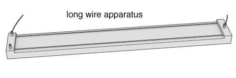
- 1 Long wire assembly
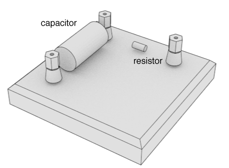
- 1 Capacitor/Resistor Plate
- 1 Multimeter
- 6 banana cables
- 1 Switch
- 1 DC Cable Assembly
Basic Concepts
Lab/Lecture
Depending on the pace to of the lecture, you might not have gotten to currents and circuits yet. That's ok! This lab should be doable and understandable without have learned this stuff in lecture yet.
Some quick definitions, since we'll use these words:
- Current: the amount of charge passing through a conductor in a given amount of time. Units are Amps [Coulombs per second] Think of it like how much water per second passes through your faucet.
- Voltage: the difference in electric potential between two conductors. Units are Volts [Joules per Coulomb]. An analogy would be the height of the water towers on buildings. The higher they are, the more gravitational potential the water has. (and the more it will loose as it falls)
- Resistance: the measure of the degree to which a conductor opposes an electric current through that conductor. Units are Ohms ($\Omega$).
The relationship between these three variables is quite simple - it is known as Ohm's Law.
Ohm's Law
Ohm's law states that the current passing through a conductor is proportional to the voltage applied and inversely proportional to the resistance.
$$ \begin{equation} I = \frac{V}{R} \end{equation} \label{eq:ohmslaw} $$Exp 1. Current, Voltage and Resistance
**Attention! READ THIS**
This lab requires that you follow the instructions carefully. Please read every paragraph and sentence very carefully and double check things before plugging them in or turning them on. If you connect something incorrectly, you might cause the entire Marshak Building to loose power. This would be devastating and it would be traced back to you work station. Just kidding. There are protections in place that would prevent it. However, please do pay attention to what you're doing. If something seems wrong, or is getting hot, or smoking, then unplug things and alert the TA.
Voltage
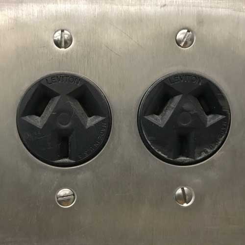
1. To do: Determine the voltage coming from the 3 prong DC wall plug. (This is not the standard looking wall socket but the one that looks like this:)
How? Do this by using the multimeter to measure DC potential. Put the two 'banana' plugs from the special DC cable into the multimeter: One should go in the COM port, the other in the port labeled with a V. Next, select the VDC symbol  from the selector knob. Make sure your multimeter reads a positive value. If it's negative then switch the two bananas.
Resistance
2a. Using the multimeter, in resistance measuring mode, measure the resistance of the little resistor on your table. It should be about 1.0 kiloOhms (1.0 k$\Omega$).
2b. Measure the resistance of the rheostat.
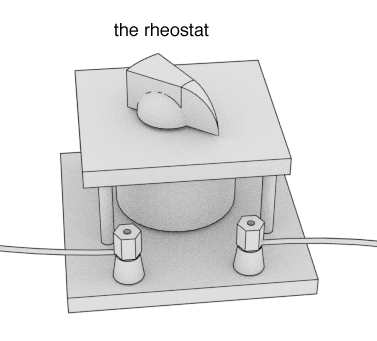
The rheostat is a resistor you can change. Turning the dial changes the internal resistance of the unit. It's also called a variable resistor. One setting on the multimeter will measure resistance. Connect the multimeter to the rheostat in such a way as to measure the resistance (Ohms $\Omega$) of the rheostat.
What's the minimum resistance of the rheostat?
What's the maximum resistance of the rheostat?
2c. Now measure the resistance of the metal wire on the long board. There are two wires, but use the multimeter to measure just one of them.
Current
Based on Ohm's Law [Eq. \eqref{eq:ohmslaw}], what will the current be if 5 volts is applied across a resistor of 1 Ohm?
What would the current be if 5 volts was applied across a 0.1 $\Omega$ resistor
3. The power supply that is creating the 5 volts on the wall can only put out a certain amount of current a given time, so if we were to create a circuit that needs more than what it can produce, then we might damage it or blow a fuse. So, we have to be careful in the next experiment.
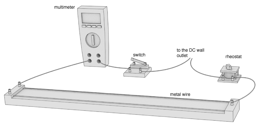
We're going to measure the current through a more complicated circuit. On the bench you'll also have a long board with two wires on it. We'll use one of the wires to make this circuit. Connect the following elements together as shown in the drawing. (Start with the switch open)
Make sure the rheostat is set to the maximum resistance (should be about 10 $\Omega$). Add the resistance of the wire and the rheostat to get the total resistance in the circuit.
If 5 Volts are applied to this amount of resistance, what current should you expect?
Go ahead and set the ammeter to measure current (A). You'll also need to press the orange button to select the DC mode for current measurement. Double check that one banana is in the COM, the other is the 10 A socket. Now, once it looks all good, close the switch and verify that your measured current is close to what you expected. If you're not sure about your setup, ask your TA for some guidance.
Physical nature of resistance
This part of the lab will determine how the resistance of a wire depends on its length. One more definition:
- Resistivity: the measure of the resisting power of a specified material to the flow of an electric current. Units are Ohm meters: ($\Omega \; m$)
Resistance vs. Resistivity
About these two words.
They sound similar but mean different things. The Resistivity (\rho) is a property of all pieces of copper, while the resistance (R) would be the property of a specific piece of copper, say a 1 cm cube. Resistivity is a property of a material while resistance is a property of an actual thing. The are related via: $$ R = \rho \frac{l}{A} $$ where $A$ is the cross-sectional area and $l$ is the length of the object (in the direction of the current flow)
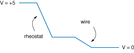
The next thing to do will be to measure the potential drop along the wire. The image below is an abstraction of what is meant by voltage drop. The currents starts at a high potential, of +5 Volts. It then moves through the rheostat heading towards a lower potential. The potential drop across the rheostat is shown by the first downward sloped line. After the rheostat, it moves along the conducting wire (no voltage drop) and then is reaches the long wire which has a small resistance. There another voltage drop occurs which brings the potential to zero.
Based on your measurement of the total current passing through this circuit, and Ohm's law, calculate the voltage drop across the rheostat (when the rheostat is set to its maximum resistance of 10 $\Omega$.)
Now, what do you expect the voltage drop across the long wire to be?
Let's measure it!
Disconnect the multimeter from the circuit, and connect the switch directly to the end of the long wire. Also connect the COM port of the multimeter to that end of the wire. With the multimeter in voltage measuring mode (don't forget to switch the wires), use the little metal slider to measure the potential at 10 cm increments along the wire.
You should eventually get a table of data that has two data points: voltage and position along the wire.
Report Question: What is that wire made of?
Most conductors we use for wires have very small resistances (< 1 $\Omega$). However, the long wire in the experiment had a larger than normal resistance. Let's figure out what it is made of.
Use this table of data to calculate the resistivity of the wire. Look up this value to determine what the wire is made of.
Some helpful math: $$\begin{equation} \frac{\Delta V}{\Delta R} = \frac{dV}{dR} = I \end{equation} $$ but $\rho = R \frac{A}{l}$ where $A$ is the cross sectional area of the wire and $l$ is the length. Thus, we can say: $$\begin{equation} \frac{dV}{dR} = \frac{dV}{d(x \rho / A)} = \frac{A}{\rho}\frac{dV}{dx} = I \end{equation} $$ The value of the current through the wire is $I$, and is something you measured earlier. The value of the $dV/dx$ is the slope of the line of your table of data. $A$ can be obtained from the diameter of the wire which is 750 μm. The only unknown is $\rho$, the resistivity.
Report Question: Why does this wire exist?
Normally, we want wire to be very conductive. Do some research and learn what applications exist for the type of wire in the long wire apparatus. Report on your findings.
What's next
The first section should have only taken about an hour, if that. Use the remainder of the time to explore the signal generator and the oscilloscope because you will need these for the next two labs.
Get to know the oscilloscope and signal generator.
The previous experiment relied on using DC power - the voltage was constant over time. However, most electronics applications involve understanding how voltages and current change with respect to time. To measure this, we could us the multimeter and a stopwatch, but a much better way is to use the oscilloscope. The other piece of equipment is the signal generator. This allows you to create time varying potentials and currents.
Here is an introduction the oscilloscope and the signal generator. Spend the rest of the period going through this document and making sure you can a) create time varying signals on the signal generator and b) measure them with the oscilloscope. The next lab will presume you know how to use the two instruments.